Our related software: immersive FIBER
Simulation of short fiber reinforced injection molded parts with static or thermal loadingXXIV. FEM-Kongress Baden-Baden, Germany 17./18.November 1997 Gerhard Schmöller AbstractParts made of short fiber reinforced plastics are widely used in different industries according to their good mechanical and thermal properties and their suitability for high volume production based on injection molding. As a further plus, when using a thermoplastic matrix they are better recyclable than other composite materials. While there are usable and tested methods (both analytical and based on FEM) for laminates, efforts to predict the mechanical and thermal behavior of parts made of short fiber materials are still in the beginning, which is mainly due to a lack of available commercial software offering this possibility. Below, a survey of existing theories and methods concerning this field will be given and possibilities will be shown to implement these methods in todays CAE applications. Material behavior of short fiber reinforced plasticsAs it is true for all composit materials the mechanic and thermal behavior of the compound is a result of the interaction between the single components, in this case betweeen fiber and matrix. Assuming a random orientation and homogeneous distribution the resulting quasiisotropic behavior is easily handeld concernig both simulation and testing. Similar is true for aligned laminats with transversal isotropic behavior, where the fiberorientation is known and a set of material data parallel and perpendicular the fiberorientation will be enough to describe the behavior of the part. In contrast to this, the fiber orientation and distribution in parts made of SFRTs is highly dependent on the molding process and therefore nearly impossible to predict. To come to a material description usable in FEA, the following problems have to be solved:
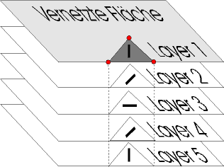
Determination of Fiberorientation and -distributionIn the past, the main problem concerning the calculation of short fiber reinforced parts certainly was the determination of the local fiberorientation and distribution. Many experimental attempts were made to meassure these quantities (e.g. using X-Ray or image analysis on cutting planes). Beside of the costs of these methods - and ignoring the fact that there has to be a real part, which is contradictory to the aim of most simulations-, converting the results to CAE formats still remains a problem. Since a couple of years however rheological programs such as Moldflow™ and C-Mold™ are available, which are mostly used to optimize the molding process. Some of these systems in addition allow the calculation of fiber orientation and distribution. These kind of programs mostly use triangular shells with several layers across thickness. This way it is possible to take into account the different fiber orientation across the thickness. Corresponding elements are available for most classical FEM solvers, making a direct transformation of results possible.
Fig. 1: layered shells with different material orientations Nonisotropic behavior of fiber reinforced materialsComming to the second field of problems, a short recapitulation of the basics of non isotropic materials may be helpful.
Fig.2:engineering constants dependent on fiberorientation A materials mechanical behavior can be specified using the stress strain relationship.
In the most simpel case of linear elastic, isotropic material with single axis loading this
relationship reduces to
To describe the most general case in space, independent of the material law one needs the strain vector, the so called constitutive matrix and the stress vector. In contrast to isotopic materials where the material behavior is independent from the direction of the applied force, the strain answer will vary with direction using orthotropic or anisotropic materials. Viewing at a single fiber-matrix-cell the behavior can be regarded to be transversal isotropic as a special case of orthotropic behavior. This is the case if there is a isotropic plane for each material point in the part. In the plane perpendicular to the fiber, the material behavior is direction-independent. That is, the stress-strain-behavior with tension in the 2-direction will be equal to that in 3-direction (not shown here). Thus the material in the 2-3-plane is isotropic (Fig. 2). Therefore only five independent material constants are needed to describe the material behavior (orthotropic matererials need 9 and anisotropic 21). The stress-strain-relationship for linear elastic, tranversal isotopic materials may be therefore given in the following manner:
The determination of the engineering constants E1, E2,, n12, n23 und G12 may now be done using experimental data or following theoretical considerations. Micromechanical description of fiber reinforced plasticsThe theoretical way follows so called micromechanical approaches which try to predict the mechanical and thermal behavior of the compound using the (isotropic) data of the composits fiber and matrix and thus reducing the testing costs, because direction dependent experiments are not needed. In addition, changes in fiber length and diameter, as well as in fiber fraction can be easily considered. Mechanical BehaviorLooking at the mechanical behavior the approach from Halpin und Tsai /6/ is commonly used ( l fiberlength, d fiberdiameter, Vf fibervolumefraction, index M: matrix and index F: fiber):
The shear modulus within the 2-3-plane may be obtained following Halpin and Kardos /6/:
Poisson's ratio is commonly determined by a rule of mixture /6/:
There are other theories concerning micromechanics of composits, giving Tandon & Weng /10/ and Cox /8/ as an example. Thermal BehaviorAs an example for calculating the thermal expansion coeffizients in a corresponding manner, the approach of Marom & Weinberg /5/ will be explained here: Assuming unidirectional fiberorientation the thermal expansion coefficient parallel fiber is
and for that perpendicular fiber they give
Other approaches are known from Cox /8/, Scharpery /4/and Schneider /9/. Use of experimental DataMeassurement of mechanical and thermal material properties of fiber reinforced materials depending on fiber distribution, orientation and volume fraction as well as temperature is very expensive. One main problem is the production of specimens with sufficiently alligned fibers. Suitable production may assure high grades of fiber orientations in the central layer, but the nearly orthogonal orientation in the boundary layers is hardly to avoid. To find a remedy costly mechanical removing of the boundary layers is needed. To determine the material constants in dependency on orientation the specimen are taken from plates with high orientation in the main direction and perpendicular. Thus a set of values is obtained which corresponds to that calculated with micromechanical approaches. Transfer to non unidirectional Fiber OrientationThe discussed micromechanical approaches mostly suppose unidirectional fiber alignment. Meassured values also are given this way. In reality allignment of the fibers will exist between these extremes. So called macromechanical approaches are used to transfer the results from the unidirectional case to different fiber alignments. Given the angle of the main fiber orientation and the percentage of fibers aligned in this direction and perpendicular, a kind of rule of mixture may be used to achive an estimate of the resulting composite behavior:
FOR1 und FOR2 are the percentage of fibers in the respective direction. The other thermal an mechanical values are obtained accordingly. FE simulationBased on the calculated fiber orientation an distribution and using the delivered micro and macromechanic methods a consistent set of orthotropic values can be obtained for each element. Thus, all needed material data needed for static and thermal analyses (material orientation, thermal and mechanical properties parallel and perpendicular to fiber direction) are available. In practice some points still cause difficulties:
The following example with a simple plate (150 x 200 x 5 mm) shows the proceeding when combining the above:
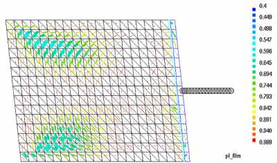
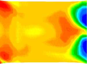
Fig.3:Fiberorientation and distribution (central layer)
Fig.4:materialorientation with respect to production
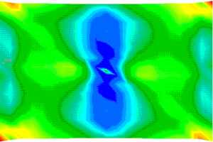
Fig.5:Plate under tension (von Mises stresses in the boundary layer) Further improvements may be achieved according to the following steps:
ConclusionGiven the possibility of calculating fiber orientation and distribution of molded short fiber reinforced parts with rheolocic software the prerequisites are met for thermomechanical simulations with parts made of these materials without to much simpilification with common FEA solvers. Thus, a closed solution within existing CAE environments is possible. Solely the lack of commercial interfaces still prevents all day use. Micromechanical approaches reduce the number of needed material constants and even allow the prediction of changes in the parts behavior caused by changes in fiber volume fraction or fiber length. Literature
|