| |
|
Finite Elements Analysis of Shrinkage Mechanisms of Adhesives during Curing
Translation of the original german paper in ADHÄSION kleben & dichten 10/2001
Thorsten Böger 2, Klaus Dilger 1, Gerhard Schmöller 2
1 Lehr- und Forschungsgebiet Klebtechnik, RWTH Aachen, Pontstr. 51/53, 52062 Aachen, Tel: +49 (0)241 80 93300
2 immersive SIM engineering GmbH, Frankfurter Ring 81, 80807 München, Tel: +49 (0)89 358 058 90
Abstract
In principle all adhesives exhibit chemical shrinkage mechanisms during the curing phase resulting from chemical networking processes of the molecules. This leads to deformations and residual states of stress in the adhesive component, which can impair the tolerable level of stress and functionality (e.g. adhesive markings with outer skin panels in automotive industries). In case of hot setting systems different thermal expansion properties of the parts additionally result in reactive forces during cooling phase. How can this effect be calculated in FE simulations?
Introduction
Especially in automotive industries adhesive technologies are being used in increasing scope. A strong trend can be observed to structural adhesive bonds with strength transmitting function. One of the main advantages of adhesive technologies is the possibility to join different materials without drillings weakening the structure (screws and rivet joints) or negative effects of the heat affected zone with welded joints. By this, the lightweight construction potential of highly developed materials, such as light metal alloys, high-strength steel and short-fiber reinforced thermoplastics (SFRT) can be used effectively.
Within industrial practice different adhesive systems with in part strongly different thermal and mechanical properties are used, optimized for the relevant specifications (e.g. EP, PU and rubber basic systems). To join the parts, the monomer or pre-polymerized adhesive is being activated by specific mechanisms (e.g. heating, ultraviolet curing, etc.), initiating chemical networking of the molecules. In this phase a compaction of the adhesive occurs, accompanied by volumetric shrinkage. For hot setting epoxy resin systems, a volumetric shrinkage in the order of magnitude of 1 to 5 % can be assumed [1, 2, 3, 4]. Thereby, the strength behavior of the hardening adhesive is being developed steadily, leading to increasing force feedback effects. Complex states of stress and deformation are initiated by shrinkage mechanisms, resulting in a "frozen" state of stress after completely cooling-off the parts (residual stresses). As a function of chemical base and additives, the maximum attainable strength of the adhesive is reached after some time (minutes or days). In this time relaxation effects in the adhesive can reduce critical stress peaks.
In this paper, a finite elements simulation methodology (FEM) of the chemical shrinkage process during curing phase is presented by the example of a hot setting adhesive. So far, FE calculations of adhesive joints usually are performed under the assumption of completely reacted systems by choosing a suitable material model (elastic, elastic-plastic, viscoelastic, etc.). By doing so, all calculations refer to stress and strain free (initial) states, and thus completely neglect "frozen" states of stress and deformation within the adhesives. In reality, it is possible that adhesive joints preloaded by residual tensile stresses break down early when additional tensile stresses occur under operating conditions (local cracking, leakage). In case of optically critical components (e.g. outer skin panels), adhesive markings due to chemical shrinkage, which can impair the quality of the component, are an important aspect for the technical designer.
Quite generally it can be said that the knowledge of critical stress and strain distributions under operating conditions is an important means for the technical designer during the qualifying phase of the component (superposed stress and strain status). If FEA is already used in early design phases of the product development parallel to CAD and prototype tests in the sense of a closed-loop design, an optimized product can be brought to market in less time (figure 1).
fig. 1: "Closed Loop"-Design Chain [4]
FE simulation methodology
As a concrete example for the technical problem described above, a simplified model of an adhesively jointed planking module (material steel) is being simulated to get a numerical prediction of the residual states of stress and deformation within the part (figure 2). Here, the adhesive film (epoxy resin) has a thickness of 4 mm, and the thickness of the metal planking is 0,7 mm. The simulation methodology developed here can be assigned to simulations of other adhesives as well. With more accurate material and process data available, it is possible to get an idea about adhesive markings by means of FE simulation.
fig. 2: investigated model (according to [5])
The simulation is being split into three steps:
- In step 1, heating-up of the parts from room temperature is calculated (activation of the polymerization of the adhesive by heat, here T = 121 �C).
- Step 2 (slight temperature drop within curing time) is used to describe the ad-hoc birth of the adhesive at a low temperature difference of DT = -1 K.
- In step 3 (cooling-off phase) the system is being cooled off to room temperature.
The following simplifications are made through the simulation:
- the birth of the hardened adhesive occurs abruptly and homogeneously within step 2 at DT = -1 K.
- the mechanical and thermal properties (E, n, a) of the adhesive are assumed to be temperature independent.
Then, modeling the reactive shrinkage is performed by assigning different material definitions (materials A, B and C) to the adhesive elements in particular simulation steps (figures 3 and 4).
fig. 3: process steps (according to [5])
| Adhesive properties during stepwise simulation: |
![Zuweisung unterschiedlicher Materialdefinitionen für den Klebstoff in den Simulationsschritten [4]](FE-Simulation-Schwindung/abb4.gif)
fig. 4: stepwise different material properties of the adhesive [4]
Material A describes the adhesive in its initial state (monomer or pre-polymerized form) in step 1 (heating-up phase). Since in this state the adhesive does not contribute to any formation of structural stresses or strains, the adhesive elements could be eliminated completely. For simulation concerns, it is necessary to consider the displaced, but stress and strain free nodal configuration of these elements after heating up the parts to T = 121 �C for activation in successive steps. To do so, the relevant elements are replaced by "dummies" showing negligible mechanical interaction with the expanding parts combined with a thermal expansion coefficient equal to the metal components. Under these circumstances, the nodes of the "dummy" elements participate in the displacements of the parts without causing any internal mechanical loads. The simulation of step 1 is being performed from room temperature up to T = 121 �C.
Material B defines the adhesive during the simulation of step 2 (ad-hoc birth of adhesive elements within DT = -1 K). The amount of chemical volumetric shrinkage, evol,r, is the basis for these calculations, so it should be measured with care. Since chemical reactions and effects cannot be integrated directly in FE analyses at present, evol, r is being converted to an equivalent thermal expansion coefficient ("reactive coefficient" aK,r) (figure 5). Assigning this specific value to the adhesive elements in this step makes sure that the reactive shrinkage of the adhesive is represented correctly by matching thermal properties (assuming thermally isotropic behavior).
|
Assumptions: reactive volume change: isotropic reactive length change: mapping the reactive length change to a thermal length change: Definition of the reaction coefficient a K,r: |
fig. 5: calculation of the equivalent reaction coefficient according to the reactive volume change aK, r [4]
With this material definition, a thermal expansion coefficient equivalent to the volumetric shrinkage is activated within a temperature decrease of DT = -1 K in step 2 of the simulation. Compared to a realistic thermal expansion coefficient of EP (ca. 10E-5 K-1), a similar thermal shrinkage would appear at a temperature difference of DT = -67 K. Within the simulated temperature decrease, the status of the jointing parts is being influenced in negligible way. All over, the adhesive elements activated at the beginning of this step have a reference temperature of 121 �C. The metal parts have a reference temperature equal to room temperature! [4, 6].
Material C (step 3, material data as described in figure 6) defines the adhesive in its final state characteristics during cooling-off phase simulation. With this example, the cooling-off phase lies in the range of T = 120 �C down to room temperature. In case of temperature-dependent thermal and mechanical properties given for the adhesive (highly recommended!), theses data can easily be integrated to improve numerical accuracy. That leads to increasing efforts in measuring requirements, but a significant improvement of exactness can be achieved with respect to in part profoundly different material properties of polymers on the other hand (e.g. TG).
| Material properties of a typical epoxi resin | |||||||||
|
|||||||||
| Blanks: Steel | |||||||||
|
fig. 6: assumed material properties (adhesive during cooling)
As external loads only the changes in temperature within each step are being prescribed homogeneously for the entire model. To prevent the nodal displacements from being superposed by effects resulting from further fixation, boundary conditions are only given for the two flange areas. By this, the simulation of residual stresses by volumetric shrinkage mechanisms can be analyzed unaffected by other mechanical constraints (figure 8). More complex models, such as crimped flange zones with relevant mechanical constraint forces can be assigned to this simulation methodology without great problems.
fig. 7: stepwise simulation
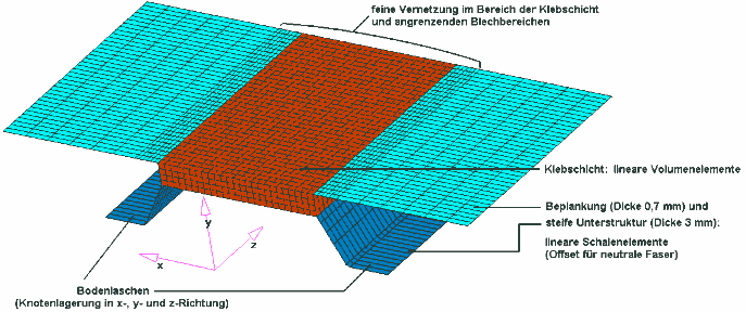
fig. 8: FE model
Results
As shown in figure 9, the meniscus-like deformations at the edges of the adhesive layer resulting from the simulation of the reactive (ad-hoc birth of adhesive elements at DT= -1 K, material B) and thermal (cooling-off phase, material C) shrinkage behavior can be clearly recognized. To get an idea about the stress situation in in the adhesive layer, the fringe plots also contain information about von-Mises stresses after completely cooling-off the parts (end of simulation). In this state, the adhesive layers may experience further stresses and strains in following production steps (adding mechanical parts, welding, etc.) or under operating conditions (high/low temperatures, external loads), which can lead to (local) failure of the adhesive joints.
In figures 10 and 11 the deformations and stress distribution (von Mises stress) of the planking is illustrated. Figure 11 shows the possibility of adhesive markings in a largely scaled displaced configuration plot.
fig. 9: calculated deformation and loading of the adhesive after cooling stage (magnification 25 times)
fig. 10: calculated deformation and loading of the blank after cooling stage (magnification 25 times)
fig. 11: as fig. 10, magnification 250 times
Perspective
With the FE simulation methodology described in this paper, it is possible to predict the effects of volumetric shrinkage mechanisms of adhesives during birth of the adhesive itself. Thus, the technical designer gets an idea about residual stresses, helping him to build an improved prototype for test series. Starting from this preloaded initial state, and not being forced to use the stress and strain free initial configuration of the adhesive, gives the possibility to predict thermal and mechanical effects on the complete module, resulting from further production processes and operating conditions. For automotive industry concerns, this method helps to get an idea about adhesive markings with optically critical parts, such as outer planking modules. Here, the accuracy of numerical results strongly depends on the quality of the prescribed material data.